Forklift controller
Dec 6, 2009 Electronic Projects
This entry should pull together all the things in my web site name.Bunch of electronics, code, and some machining to make it fit.
I have a 30+ year old fork lift at my shop that died. It was basically given to us to use for storing it by someone who got it for free.
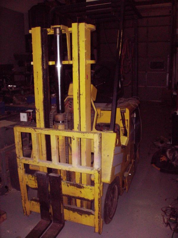
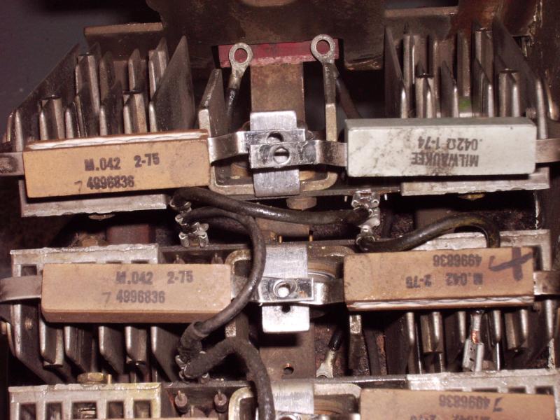
It was broke when we got it and I got it working whit the original electronics. It has a blown transistor and huge diode that I replaced and it worked for about a year until it finally gave up. The main power section was made up of 16 large PNP transistors (they actually had International Harvester part numbers on them, didn’t know they did electronics!) and all of them were dead along with the 16 low ohm high wattage resisters that tied all the sections together and acted as fuses.
Partial picture:
I started looking for replacements and found them at NTE for over $20 each and the resisters were no longer available. So rather than patching it back together for over $300, I decided to design my own.
I found a simple design at http://www.zeva.com.au/speedy/ and up-scaled and modified it for my use. This is the highest power circuit I have ever done, so it was something new for me. Also it is the first time I used an AVR. Using what I could find out about the original control, I determined I wanted about 400 amps at 36 volts. I took this from the original transistor ratings and the fact there is a 3?0 amp main fuse. (couldn’t read it) It powers the drive motor as well as the hydrolics. This is probably a bit over kill, but better to be safe. This also worked out well since I spec-ed out reasonably priced FETs that are 50A each, so 8 would give me 400A and an even number to drive.
The first version was built using the heat sinks and other bits form the original control and lasted about 30 seconds.
Pilot error. Looked like mini flash bombs at a rock concert! 8 FETs later and some fine tuning and I got it working for about 6 months. It finally died so I decided to take another whack at it. In the interim I ran across this tread paul-sabrinas-cheap-144v-motor-controller which basically started out the same way I did but took it much further with a lot of community support.
I have tried to do this on the cheap using what I have available, so I started with the heat sink that was salvaged from an old forklift charger. It also worked out since 6″x9″ is the largest board I can easily etch. From there I tried to correct the errors I made on the first version.
First, I totally under designed the power supply section. It got upgraded with pass transistors to give me a stable 12v gate supply. This was causing the FETs’ gate siginal to be crappy and the main cause of the failures.
Second, the first design had the FETs mounted on the separate heat sinks from the original controller. This gave different gate lengths and added more noise.
Third I had some bad code. After looking at the “Cougar” design I found a few flaws I had.
I ended up with this:
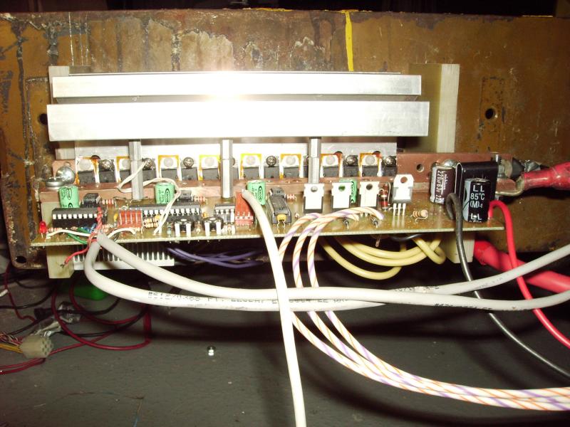
I also added a serial port so I could monitor things real time.
One big difference from the “Cougar” is I am using the original current shunt to measure current. My code is not as sophisticated since I am simply sensing over current or high temp and shutting things down instead of adjusting the output. I am also controlling the reversing solenoids with the micro. I do not have such large ripple caps since I am still using the HUGE ones from the original as well as the freewheel diodes in parallel with the ones on the controller.
So far I got it running pretty smooth. Good power, no noise, staying cool.
I’ll see how it goes and report back how it works out.
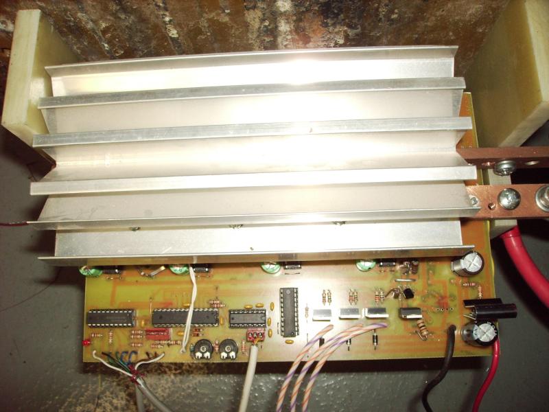
Here are a few more pics of the work in progress.
A few more pictures


