Boardtools v0.8 (FINALLY!)
Aug 16, 2014 Computers, Electronic Projects, Linux
I have finally gotten around to cleaning up the script I use to generate gcode from Kicad and engraving files. (Since someone finally commented on it and asked for the new version)
I have completely re-written it and added a bunch of new settings. It is now one huge script instead of several smaller ones and has grown nearly 3 time the size (over 3600 lines!)
There is a quick README and crude INSTRUCTIONS included to help explain the changes and how it works.
It is not fully tested by any means, I still keep finding, changing, and correcting things, but I ‘think’ it is user friendly enough for others to find useful.
Many of the changes and setting were done so it would work with the new mill I have and are a bit specific to it, but they may be useful in other ways as well and generally made it more flexible and capable.
If you are one of the silent few who used the first version, your config files will probably not work as there are new setting that will be missing and a few renamed. You can open them in a text editor and figure out what your old settings were.
There are a lot of things it can do that I haven’t documented well, but the basic instructions should get you going. If one of the settings is not clear, please ask and I will try to explain what it is for. Some may simply not make sense for your application.
Please, if you give it a try and find it useful, or not, or find a bug, PLEASE let me know. If it is a ‘bug’ and not a ‘feature’ ![]() I may try and fix it. If you have a reasonable request I think would be useful, I may try to add it in. I wrote this for my own use, and it does what I want, but you may think of something I would like it to do in the future.
I may try and fix it. If you have a reasonable request I think would be useful, I may try to add it in. I wrote this for my own use, and it does what I want, but you may think of something I would like it to do in the future.
Download: boardtools-08.tar.gz
Tick, tick, tick…
Apr 11, 2014 Computers, Electronic Projects, Home Projects, Linux, MythTV, Programming, Rain Barrel
My, how time flies.
I need to catch up on a bunch of stuff soon.
- First, I have started building custom K-Cup holders called the Kupousel. Please check them out.
- I have spent a lot of time with my “new” CNC’ed X2 Mini-Mill. Lots of mods and stuff I hope to post about.
- Sill making Tonal Insanity effects pedals. The mill is helping with them. Started using surface mounted components.
- Got my hands on some Arduino knock-offs and been using them to develop other AVR stuff.
- Built an SMD reflow oven from a toaster oven and a ATmega for a PID control.
- Built (cobbled together) a new spindle for my old router when the Roto-Zip started to give out. It also has less run out so I can route PC board directly now, even SMD stuff.
- Completely re-written my Board Tools program with even more options, partly to take advantage of the new spindle and mill.
- Will be re-re-re-building the rain barrel yet again this year. Last year I tested a control using a pico-power ATtiny13a AVR. Worked well, needs a bit of fine tuning. Main reason for rebuild is the barrel cracked, I moved the garden, and I dropped the solar panel at the end of last year and broke it.

- Building my daughter a loft bed – out of an old desk.
- Rebuilt my MythTV system and got in a fight with the stupid cable box that uses XMP IR protocol. (on going)
- Oh! It has been so long I never mentioned my new main computer: 8-core! AMD “Bulldozer” FX-8120, liquid cooled, msi 970A-G46, 16GB RAM, 1TB HD, Bu-ray burner, 23″ wide screen monitor, running Fedora 19 (20 soon). It F…’IN SCREAMS! Built Android (for A10) complete from source in a few hours! That was why I got it thrown in on a job to modify a Mele A2000 STB into a network/web based, Scent Palette controller. Builds MythTV in about 10 minutes.
Hopefully I will add more info in less than the next 2 years! ![]()
PC Board Tools
Mar 23, 2012 Electronic Projects, Programming
Here are the scripts I use to convert PC boards from Kicad to G-code.
http://www.lwill.net/downloads/boardtools-01.tar.gz
This is the README included for information.
README 03/28/20012

Tested with LinuxCNC 2.6.0~pre and KiCad (2012-01-19 BZR3256)-stable and
    pcb2gcode 1.1.4

### DISCLAIMER ###
CNC MACHINES CAN BE DANGEROUS!!!
THOROUGHLY CHECK AND TEST ANY CODE BEFORE RUNNING!!!

Files included in boardtools directory:
doall.py                    GUI front end for pcbbatch
pcbbatch.py                 Batch file to run all programs using config file
boardcfgdef.py              Default config file
Etch_Z_adjust.2.2.cl.py     Modified command line version
gerber2emc2cl.py            Modified command line version
p2gdrillopt.py              For optimizing drill files
p2gpathopt.py               For optimizing paths
demo                        Directory with sample Kicad layout, gerbers, and
                            sample boardcfg.py for testing

REQUIRED:
python-argparse
pcb2gcode installed on system
EMC2/LinuxCNC 2.5+
KiCad

Optional:
opti  (from Etch_Z_adjust)  Untested, I have not used it, not included

-Quick and dirty:
Extract.
For GUI, from boardtools directory run:

$python doall.py

    You will probably need to run doall.py at least once to verify default
    file paths. Save defaults to boardcfgdef.py in installed directory.

To try demo:
    Click "Load boardcfg"
    Open the demo directory and choose boardcfg.py
    Click "Default Paths" and set to the correct locations.
    Click on "Browse" under "Board back" and reselect "demo-Back.gbl"
        to make sure the path is working directory is correct.
        This will automatically set the other files correctly.
    Click "Run boardcfg" (it will automatically ask you to save)
    Check out the generated files!

To run a config file from a project directory:

$python boardcfg.py

-The idea:
Generate ready to run g-code files from KiCad for LinuxCNC using one interface.

-The method (how I do it):
Schematic and board layout with KiCad.
    I use the Comment layer for text and draw board outline using actual tool
    path based on the bit I will be using so I can leave gaps to keep boards
    paneled together. (there is an option to use pcb2gcode for outline instead)
Generate gerbers and drill files (4). *Back.gbl, *PCB_Edges.gbr, *Comments.gbr,
    and *.drl
Use pcb2gcode to generate back and drill g-code files.
    * the paths are very "stair-steppy" which I did not like
Use gerber2emc2cl to generate text and outline g-code files.
Join the paths and text together in one file.
Use p2gpathopt to reduce "stair-step", smooth paths, and reduce moves.
    Due crude optimizing.
Use p2gdrillopt to due crude optimizing and optionally use only one drill bit.
Use Etch_Z_adjust (*modified) to do auto-leveling.

-The Solution:
Have a config / batch script to do all this automatically.
    In reality there is a script that is placed in the drawing directory
    that holds the configs (boardcfg.py) and calls another script (pcbbatch)
    that does all the hard work. This way boardcfg can be run in place when
    a board is modified without copying main script to each drawing directory.
    All needed settings needed to run are saved in the boardcfg.py file.
A GUI to select all the various setting and generate the config file and
    optionally run it.
Config file default name is boardcfg.py This can be modified by hand "at own
    risk" if desired, but may break compatibility with GUI. Undocumented.

-What does the work:
pcb2gcode

Etch_Z_adjust.2.2.cl.py
    Modified command line version. Added ability to re-run file without
    re-probing. Modified to use a separate probe instead of tool bit, and to
    set tool height automatically.(Must use EMC2/LinuxCNC 2.5+!!!!!! uses G10)
gerber2emc2cl.py
    Modified command line version. Added ability to mirror and offset.
p2gdrillopt.py
    For optimizing drill files. Allows using only one drill and does crude
    optimizing using Morton number.
p2gpathopt.py
    For optimizing paths. Smooths out pcb2gcode paths by finding the midpoint
    of each stair-step, eliminates redundant points creating straight lines
    within a set tolerance. (difference in slope < .001 or about .057 degrees)
    Adds very slight deviations from original, but gives much smoother result.
    You decide.
    Also optimizes based on Morton number.

-Credit where credit is due:
While thoroughly hacked and mangled, my work is based on these previous works.
Both have no copyright/left restrictions in the files.
I likewise put no restrictions other than ask for credit if you use it.
(Please visit lwill.net)

Etch_Z_adjust from michael_m at cnczone.com

http://www.cnczone.com/forums/pcb_milling/82628-cheap_simple_height-probing-11.html#post843483

gerber2emc2 from SAMMEL Lothar on the LinuxCNC wiki

http://wiki.linuxcnc.org/cgi-bin/wiki.pl?Converting_Tools

-Other software:
KiCad

http://kicad.sourceforge.net/wiki/Main_Page

LinuxCNC

http://www.linuxcnc.org

pcb2gcode

http://sourceforge.net/apps/mediawiki/pcb2gcode/index.php?title=Main_Page

-Why my settings / method seems weird:
I actually use a coated board and a drag bit to scribe the coating, then drill
    it without removing it from the machine, then etch in FeCl. The scribe
    only needs to be offset .001. The scribe and probe mount off to the side
    of my spindle, that is the reason for the offsets. I also use
    Etch_Z_adjust for engraving other things using a normal engraving bit and
    separate probe which was the original reason for modifying it.
I used the Morton number optimizing method because it was fast and simple and
    better than nothing. I may rewrite the optimizing method later.
This is my first major attempt at Python programming, so it is ugly. It
    started simple, and 1100+ lines of code later.... So don't ask why I did
    something the way I did, the answer you will likely get is
    "Because it worked!"
More info on this and other stuff at lwill.net/blog
All comments are welcome, but I reserve the right to ignore them!

I can be contacted though lwill.net
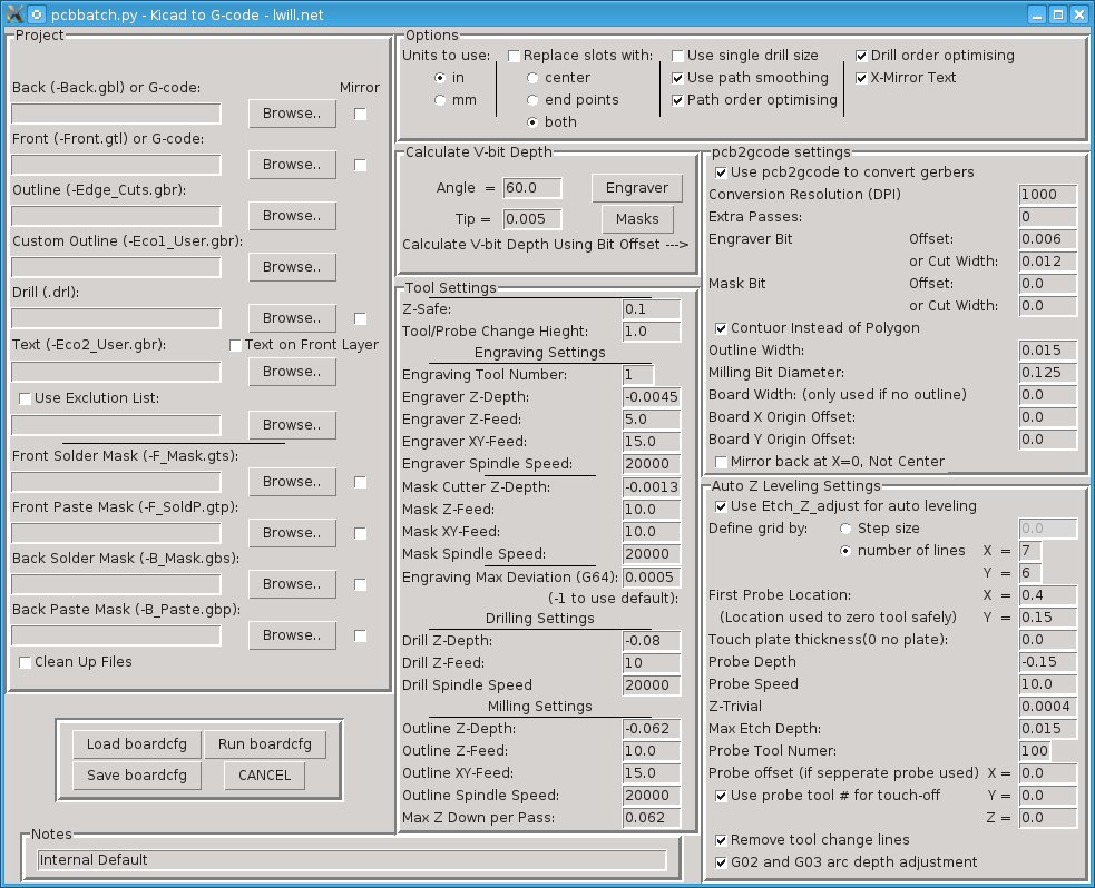
Screen shot of GUI:

Tags: electronics, pc boards, programming
PC Boards, My Way
Mar 5, 2012 Electronic Projects
I have found a new way of making PC boards.
I start with a bare board.
Place a thin layer of “secret” resistant coating on it.(on a spin coater)
Use my CNC router to “engrave” it with a drag scribe.
With out moving it, drill it and route outline.
Last etch it in ferric chloride.
Now this may seem odd at first. Why not just route the board with the CNC? Read the rest of this entry »
Let me try to explain. I have always used the photo resist method with laser transparencies and pre-sensitized boards, etched then drilled. When all goes well, the results are great. The biggest problem has always been getting a good 1 to 1 print from the laser printer. Next problem is lining the board up to drill it, which gets worse if the print was not square or to scale to begin with.
Now, my main reason is I am sorta cheep. I have never bought the right bits to do direct PCB routing. My router does pretty good, but I am just not sure how it would do, and hate to spend money just to break bits. I like the photo method, but bare boards are cheaper. There is also the fact I already have a bubble tank of etchant.
When I first started experimenting with my method I used an old photo board I had. It was a bit old, so I just tossed it in developer with out exposing it to fix the resist first. This worked, but still expensive board and the coating is very fragile and gets scratched during drilling. More on the coating later.
Tags: electronics, pc boards
Forklift controller
Dec 6, 2009 Electronic Projects
This entry should pull together all the things in my web site name.Bunch of electronics, code, and some machining to make it fit. Read the rest of this entry »
I have a 30+ year old fork lift at my shop that died. It was basically given to us to use for storing it by someone who got it for free.
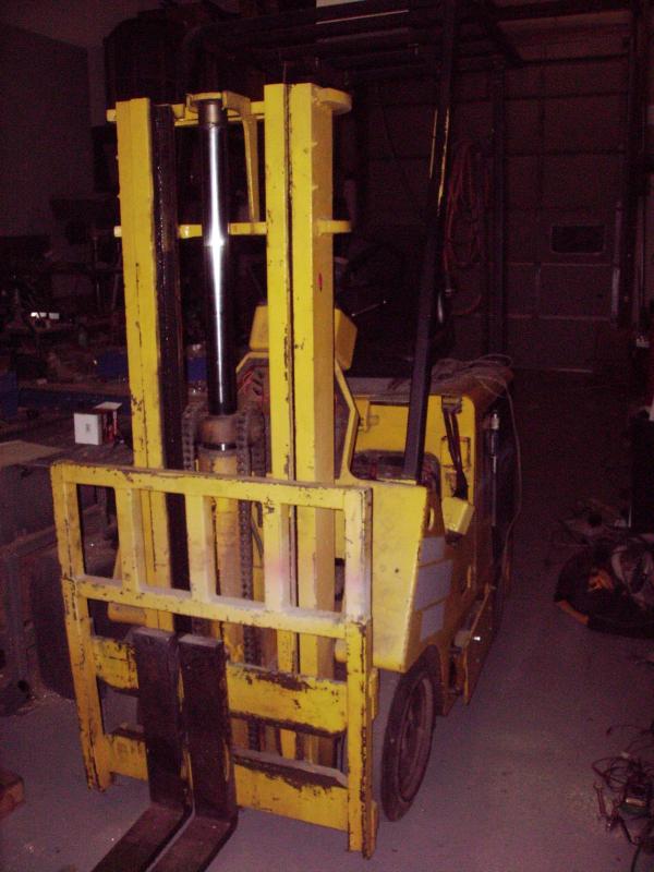
It was broke when we got it and I got it working whit the original electronics. It has a blown transistor and huge diode that I replaced and it worked for about a year until it finally gave up. The main power section was made up of 16 large PNP transistors (they actually had International Harvester part numbers on them, didn’t know they did electronics!) and all of them were dead along with the 16 low ohm high wattage resisters that tied all the sections together and acted as fuses.
Partial picture:
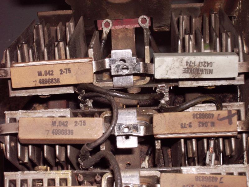
I started looking for replacements and found them at NTE for over $20 each and the resisters were no longer available. So rather than patching it back together for over $300, I decided to design my own.


