Rain Barrel Controler Design
Feb 27, 2012 Rain Barrel
This is the (current) controller design.
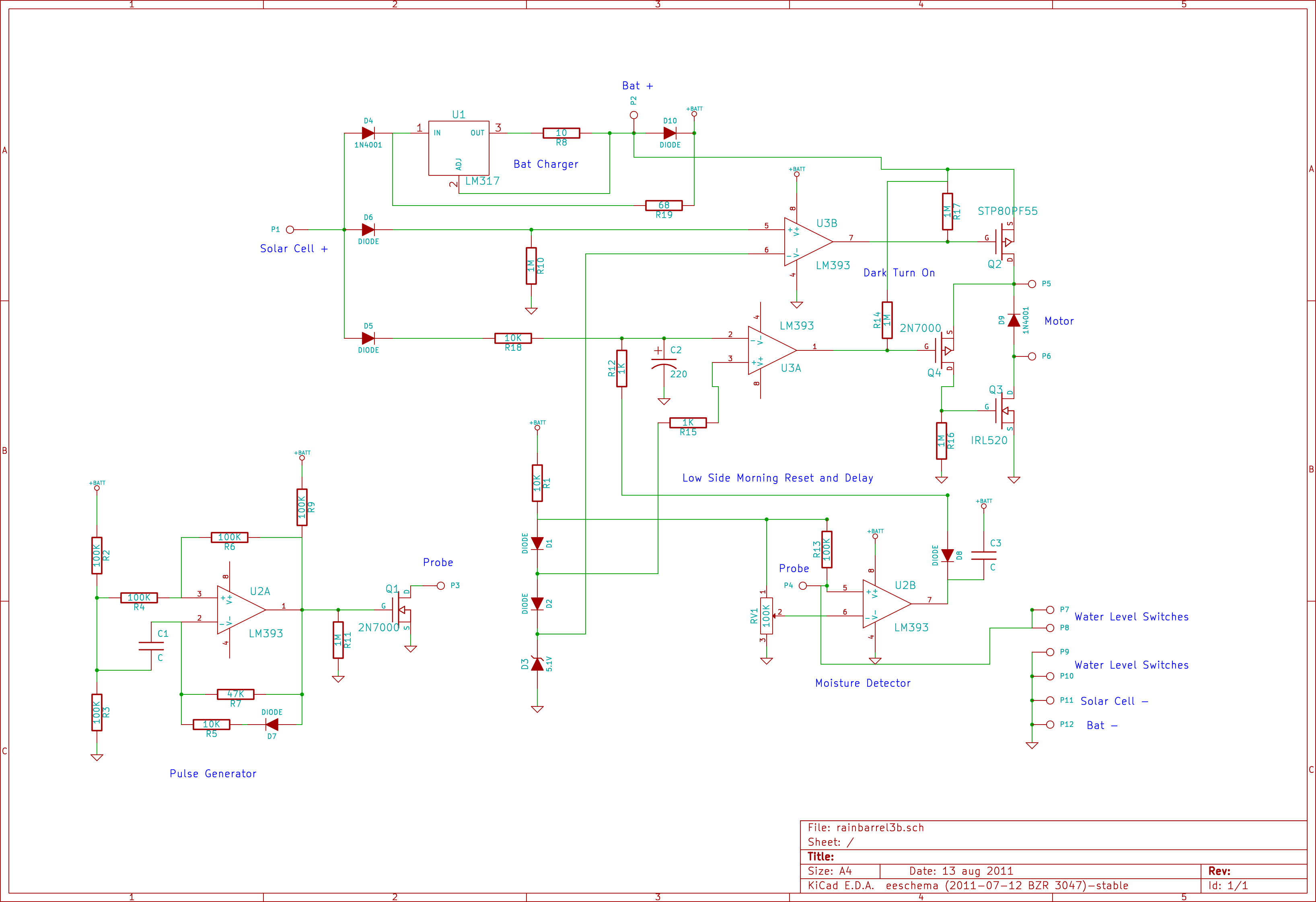
It is very crude and has not been truly “engineered”, but I kept adding bits and trying values until it did what I wanted. Most of the values were chosen from what I had on hand and drove the design.
The circuit accomplishes 3 main functions.
First: Charge the battery with the solar cell.
Second: Turn on the pump at night, run to a set level of water, turn off and not run again until the next night.
Third: Use a moisture probe to prevent running if the ground is wet enough.
The solar cell is used as a light sensor as well as a power source.
Power from the solar cell is fed to a LM317 in a current source mode to supply approximately 125 mA to the 9.6V 1600mAH NiMH battery pack. This provides slightly less than a 10% charge rate based on 10 hours of full sun a day. According to most sources I found, this reasonable charge rate without over charging, since it is time limited by the amount of sun each day and not constant. R19 provides power to supply the electronics while the sun is out, and D10 when dark and running solely from battery.
Power is also fed through D5 and D6 to a 2 part sensing circuit. D6 feeds one half of a LM393 comparator, U3B, to detect when the sunlight drops below a point set by D3, a 5.1V zener. U3B turns on Q2, the positive side of the output. D5 charges C2 and fed into U3A used to detect when the sun is shining, set to approximately 5.7V (D2+D3). This helps to insure U3A (5.7V) is on only after U3B (5.1V) turns off for the day. The capacitor forms a time delay to prevent the output staying on indefinably if the level detectors fail, setting a maximum run time. This also arms the system each morning. U3A turns on the low side driver Q3 through Q4 only when Q2 is turned on (after dark) and helps to provide a high enough voltage to turn Q3 on fully.
U2A is used as an oscillator to send a signal to the moisture probe through Q1. This helps to prevent a capacitive charge from building up on the probe and limits the current draw through the probe due to it’s duty cycle.
U2B is used for turning the system off, either with a level sensor or moisture probe. When activated, the output pulls the input to U3A low, discharging C2 and turning Q4/Q3 off. A level sensor simply pulls the input to ground. The moisture probe set point is set with RV1 and the osculations are smoothed out at the output using C3. The moisture probe may not turn the system off instantly, but since it is active even during the day, it prevents C2 from charging thus preventing the system from ever arming.
The water level sensors are normally open magnetic reed switches with a magnets mounted in floats to activate them. There is one used for the water level to dispense, and one to detect if the barrel is empty.
The moisture probe is two stainless steel wires about 2 inches long and 1/4-3/8 inch apart.
A note on the 9.6v NiMH battery life:
The pump runs for about 5 minutes MAX at about 2 amps. or a total draw of less than 160 mAh (.16 Ah). In reality it takes about 2 min. to move 10 gallons. The pump is rated at 1000 gph with zero head,(36 sec!!) but raising about 6 feet slows it down. The battery I am using is ratted at 1600 mAh so I only draw about 10% of it’s capacity. The solar cell is rated at 1.8 W or about .15 A at 12V.(it’s actual unloaded output is 18v+) Charging the battery at slightly less than the suggested 10% rate,(.16 A) it will take about 10 hours of average sunlight to fully recharge, or an average day. That still leaves enough capacity to run for a week with less than average sunlight, and a few really bright days will make up for it. If the battery should go flat, it comes with a wall charger to freshen it back up if needed. The electronics are basic very low power op-amps and efficient MOSFET drivers drawing very little additional power.
Tags: controller, electronics, rain barrel


